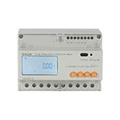
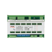
Abstract: Microcomputer protection and multi-function power meter are adopted to collect various electric parameters and switch signals of 10KV high voltage cabinet in the substation.
The system adopts the way of networking on site. After networking, communication is carried out through field bus and transmitted to the background remotely. Acrel-2000 type power monitoring system is used to realize real-time monitoring and management of power consumption in the distribution circuit of the distribution station.
Keywords: Data center; Double machine redundancy; Substation; Acrel-2000; Power monitoring system.
01 Overview
The power distribution room of the Data Center of the Financial Information Center of the People's Bank of China is located in Desheng International Center, Desheng Street, Xicheng District, Beijing. The existing power monitoring system has been in operation for 7 years. The equipment model is old, often crashes, frequently breaks down, and the operation is inconvenient.
The details are as follows:
There are 18 high voltage cabinets, 59 low-voltage switchgear cabinets, 8 incoming line cabinets, 6 capacitor control cabinets and 8 transformers in the distribution room.
In this renovation, the hardware and software of the monitoring system of the distribution room will be replaced without affecting the power supply of the machine room, and 9 environmental temperature and humidity sensors will be added.
In the case that the data collection point and the collection line are not changed, the reconstruction can reduce the failure rate of the system, operate more conveniently, function more perfect, and improve the security and stability of the system.
02 User Needs
2.1 Conduct statistics, analysis and calculation on real-time data to generate required voltage qualification rate, active power, reactive power, current, total load, power factor, large value and small value of electric quantity daily/monthly/year, time, date, load rate, logical operation value of digital input state quantity, etc., and distinguish normal/abnormal device displacement times, etc.
2.2 In order to prevent the failure of INDUSTRIAL computer in operation requires two servers to work at the same time and receive the same data.
2.3 In order to improve the reliability of collection, this project adopts the industrial gateway as the collection equipment. This gateway has data storage function and two network ports to forward data to two servers at the same time.
When one of the gateways is out of order, it is only necessary to replace the acquisition terminal to another standby gateway.
2.4 Full data backup can backup all information in the database.
2.5 Timed automatic backup can set the automatic backup cycle, automatic backup of the database.
2.6 Historical data recovery can be based on the historical data backup file for historical data recovery.
03 System solutions
The client of this project is concerned about the stability and security of the system, and requires the system and network to do double-machine redundancy processing to ensure the security of data.
In a dual-network redundant system, both the host and the slave use two network adapters and are assigned to two different network segments, with two network connections between the master and slave.
The two networks are mutually standby to ensure reliable network communication between master and slave.
The difference between dual network redundancy system and single network redundancy system is that the switch between active network and standby network is increased when the master/slave machine is inquiring the state of each other.
For example, when the backup station sends a query command to the active station through the active network, if it is found that the active station does not receive the correct response within the specified time, the backup station does not immediately judge the active station as a failure station, but automatically switches to the standby network and sends the query command to the active station again.
If the standby network communication is normal, the standby network is switched to an active network and the state of the failed network is displayed in the alarm message.

System structure topology diagram
3.1 Station Control management
The station control management is the direct window of human-computer interaction for the managers of power monitoring system.
The station control management equipment is set in the distribution duty room on the ground floor of the data center.
3.2 Network communication layer
The communication layer is mainly composed of bus network.
The main function of the bus network is to realize the data interaction between the field microcomputer protection and the station control management, make the distribution system management centralized, informationized and intelligent, greatly improve the security, reliability and stability of the distribution system, and achieve the purpose of unattended.
3.3 Field equipment layer
The field equipment layer is the data acquisition terminal. The intelligent equipment connects to the monitoring host through the screened twisted pair RS485 interface and uses the MODBUS communication protocol bus to network and realize remote control.
04 System Function
System friendly man-machine interface, visual display in the form of distribution a figure running state of distribution line, real-time monitoring of voltage, current, power, power factor of each circuit, power electric parameters, such as information, dynamic monitoring power distribution circuit breaker, isolating switch, knife, such as state, as well as related to failure, the alarm signal.
Once in power distribution diagram, when the mouse moves to near each loop, the mouse pointer to hand form, the mouse click to view the loop electric parameter in detail, including three phase current, three-phase voltage, three-phase total active power, reactive power, power factor, positive active power, 24 hours and you can view the current trend curve and voltage trend curve 24 hours a day.
System has real-time power parameters and the historical power storage and management functions, all the real time acquisition of data, order the event log can be saved to the database, such as in the query interface to the custom need to query parameters, specified time or select query recent update record data, etc., and displayed by way of the report.
Users can customize daily and monthly reports to support the export of Excel format files, and can also export PDF format files according to user requirements.
The system supports the integrity of the system with rich report volume.
The system has the function of timing meter reading and summary statistics. Users can freely inquire the electricity consumption of each distribution node in any time period since the normal operation of the system, that is, the statistical analysis report of the power consumption of the node's incoming line and the power consumption of each branch loop.
This function makes the electricity visible and transparent, and can be analyzed and traced when the electricity error is large, so as to maintain the accuracy of the measurement system.
The communication structure diagram of the system mainly shows the network structure of the system. The system adopts a hierarchical and distributed structure and monitors the communication state of the equipment in the interval layer at the same time.
Red indicates normal communication, and green indicates abnormal communication.
The system can store and manage the records of remote signal dislocations, protective actions, accident tripping, voltage, current, power, power factor off-limits and other events, so as to make it convenient for users to trace the history of system events and alarms, query statistics and accident analysis.
05 Summary
The client of this project is the power distribution room of the data center of the People's Bank of China. What the client cares about is the stability of the system equipment and the integrity of the data.
The ACREL2000 power monitoring system used in the project has the redundancy function of two machines, and the two networks are standby for each other, which can guarantee the reliable network communication between master and slave machines.
The system has timing automatic backup, can set the automatic backup cycle.
Historical data recovery, can be based on the historical data backup files for historical data recovery.